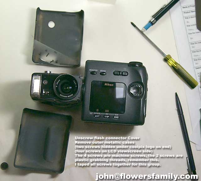
Nikon Coolpix 990 Lens dissasembly
Take serious caution when opening this lens assembly
by John Flowers
Home| |
If you are interested in Main Body disassembly, or have problems with a corroded switch, please refer to
Nikon 950 Repair by Stan Richard
Jim Betz had this to say after taking a few more steps past what I outlined here:
So I pulled out my trusty hobby phillips screwdriver set and sat down to go after it - with the idea that at least I could figure out if it was the viewfinder or not. Following John's
step-by-step was easy and my 950 was close enough to the 990 he wrote up that I got all of that done fairly easily.
When the viewfinder was out of the camera and physically inspected it didn't seem to have any problems - and it isn't
electronically connected to the rest of the camera so I suspected that the grinding rachet sound I was hearing was
unlikely to be coming from the viewfinder. But to be certain I put the viewfinder to my eye - out of the camera (after
disassembly) and saw that it was working fine. So I gave the camera the old "smoke test" and powered it up with the viewfinder
out of the camera. Sure enough the noise was still there andthe dreaded "System Error" showed up in red on the LCD (same as
before) ... and, yes, I still had to pop the battery door opento get it to power off.
If your problem is the viewfinder the camera should work
correctly - but when you view thru the viewfinder it will be
fuzzy or perhaps not even able to see thru it at all.
At this point I was ready to send it to Nikon for their free
estimate - but I knew it was expensive no matter what. So I
decided 'why not give the lens assembly a try'.
Sorry - I don't have any pics (remember my camera is what I
was working on). But here is what I did:
The 'lens half' of the Coolpix 950, 990, etc. line has 4
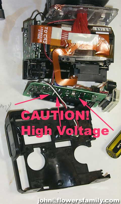
main sub-assemblies inside the case. There's the flash (CAREFUL!!
there are some HIGH voltages and relatively large capacitors
storing that voltage here), the viewfinder, the lens, and the
CCD and electronics (two boards).
The first task is to separate out the sub-assemblies. (I
won't go over the basic disassembly - John has detailed that.)
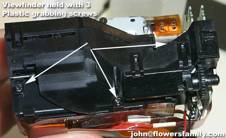
1) Remove the viewfinder per John Flowers.
2) Remove the flash by unplugging the 3 cables (two 'wire cables'
and one ribbon cable).
There are several ribbon cables. They all attach at one end
that you can get at and usually by sort of trapping the cable
in a connector that has a pressed in slide locking device. You
slide the locking device out a bit and then the cable slips out.
To put it back in you just slip the ribbon cable under the locking
device and get it all the way in and seated and then push the
locking device in to lock it down and make a good connection.
There are also some strange 'metallic' tapes that hold stuff in
place - be careful when removing these and they will go back where
they were. The adhesive on them won't be as good as it was when
your camera was built in Japan ... but it WILL hold again. I
don't know how many times you can take it apart and put it back
and still use the same tape.
3) Remove the two circuit boards - one of them is just sort of
hanging there attached by its ribbon cable. The other one
is held on by screws and the CCD is mounted to it. So be
careful not to get dirt or finger prints on the glass!
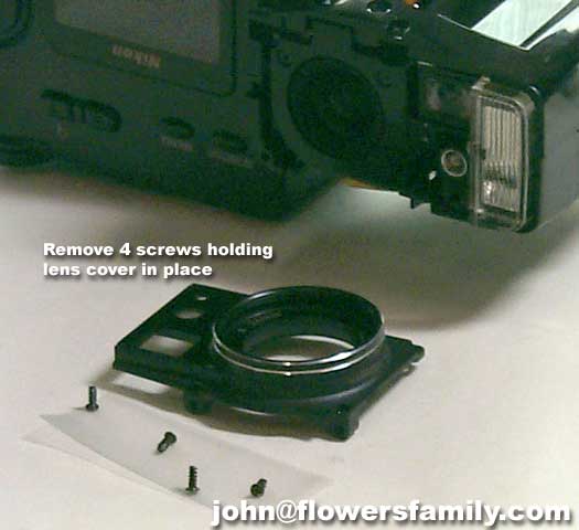
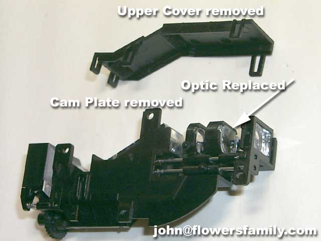
4) Remove the lens assembly.
So, in my case what wasn't working had to the be motor drive
for the lens focus/zoom mechanism. That comes out with just two
screws. After it is out you should be able to see the lens
assembly and determine if it is working correctly by sliding
the slider and seeing the lens assembly move smoothly - and
when you look thru it you will see it focusing/zooming. So I
remembered the location of the pin that links to the lens - and
it didn't seem to line up. Looking carefully at the motor and
its plastic parts I was able to determine that what had
happened is that the 'clip' that connects the motor to the
lens focus/zoom slider had 'jumped off'.
So I figured out how to get it back lined up (hint - you have
to sort of line it all up and then push on the slide pin a bit
and it will all line up just fine), reinstalled the focusing
motor, redid all of the stuff I did to get to that point (ie.
re-assembled the lens half of the camera).
Turned it on and VOILA! it works perfectly. I ran it thru some
basic tests such as auto flash, focus, close-up focus, etc. and
everything is working just as it did before. I might have even
improved things a bit because I also cleaned up some internal
dust in places such as the glass in front of the CCD and the
internal surface of the lens (the one behind the part that you
screw accessories such as filters onto).
I'm a happy camper. Copious acknowledgements to John Flowers for
his web site that gave me the courage to do this!
BATTERY DOOR REPAIR: by Shoshanna Moser
Go to your local crafts/fabric store and ask for 1/4 yard of half-inch wide
black velcro. If you don't have a needle and some black thread at home,
buy some. You'll also need a heavy duty crafts glue-- someone at the store
should be able to advise you. (You'll only need a very small amount, so
don't purchase a large tube unless there is no other choice.)
At home with your camera, the first thing you'll need to do is cut the
velcro to the correct size. Take the velcro and, starting at the back of
your battery door, run it across the door and up the front of the camera
all the way to the top. Cut BOTH sides of the velcro to this size-- it may
need a bit of trimming later on, but this will be about right.
Now, from the velcro you've already cut, take ONLY the rough, prickly side,
and cut from it a piece just large enough to cover the battery door. This
will be approximately one inch long, and after making the initial cut you
should shape it so that the piece matches the curve at the front of the
battery door.
Next, take the long, soft fuzzy side of velcro-- which should still be
approximately 4 inches long-- and attach one of its ends to the small,
rough and prickly piece you've cut for the battery door, and then sew them
together-- firmly! (This will stabilize the base of the strip and provide
the strength necessary to withstand the resistance created when it's pulled
closed.)
When this is done you should have an approximately 4-inch strip of velcro
with 3 inches bare (soft and fuzzy) and 1 inch covered by the smaller,
previously cut piece that is now sewn to it. The outward sides of this
sewn-together set should be the smooth, "wrong" sides of the velcro. Set
this aside for the moment.
From the original 4-inch strip that you originally cut you should still
have remaining an approximately 3-inch piece of the rough, prickly
side. Cut this piece so that it will cover the area from the bottom of the
soft, rubber-like casing just *above* the battery compartment on up the
camera to the point at which the casing edges outward.
It will roughly parallel-- and extend beyond-- the ergonomic purple grip on
the inward side of the casing. Once the strip is cut, you may wish to
tailor it a bit to achieve a smoother fit. Remember that the rough,
prickly side will be facing OUTWARD.
Now you're ready to glue.
Using your craft glue-- and please follow the directions provided on the
packaging -- apply glue up the front of the rubber casing-- this is where
you will attach the strip you just cut. When the glue is in place,
position the velcro strip-- rough, prickly side facing outward-- and hold
it in position for a minute or two so that the glue will have a chance to set.
With that done, apply glue to the outside of the battery door. Don't be
too stingy in its use-- this is going to have to stand up to a lot of
pressure. Once the glue has been applied, take the sewn-together pieces
and position them so that the BACK of the SMALL PIECE is glued to the door.
If you've done this correctly-- as you no doubt have-- the soft, fuzzy
piece will extend well out beyond the battery door and, when the glue is
dry, will be ready to attach to its matching side, glued to the casing of
the camera body.
Now comes the tough part-- you'll have to wait 24 hours before using your
camera. The glue will need that time to cure. But when it's done, you'll
have a camera door that works properly, holds the batteries in place, and
will serve you very well. I came up with this solution for my camera two
year ago, and haven't had a problem since.